A three-story mixed-use project off Apalachee Parkway ran into trouble when test borings hit a soft clay lens at 12 feet, right above a weathered limestone pinnacle. The original spread footing layout would have placed columns on materials with a bearing capacity differential exceeding 2,000 psf across less than 30 feet—an invitation for differential settlement that no partition wall tolerates. The design team shifted to a rigid mat foundation, integrating the elevator pit and grade beams into a single monolithic pour that bridged the erratic subsurface. In Tallahassee, where the Hawthorne Group’s interbedded clays and carbonates create exactly this kind of vertical irregularity, raft foundations are not an overdesign; they are the rational response to a stratigraphy that refuses to be uniform. Our laboratory runs consolidation and swell tests under ASTM D2435 and D4546 on undisturbed Shelby tube samples to feed the soil-structure interaction model, because guessing the modulus of subgrade reaction from blow counts alone is not an option when the clay fraction exceeds 40 percent.
A rigid mat does not eliminate risk; it redistributes it across a larger area, buying time for the soil to mobilize strength that isolated footings never reach.
Our approach and scope
Local ground factors
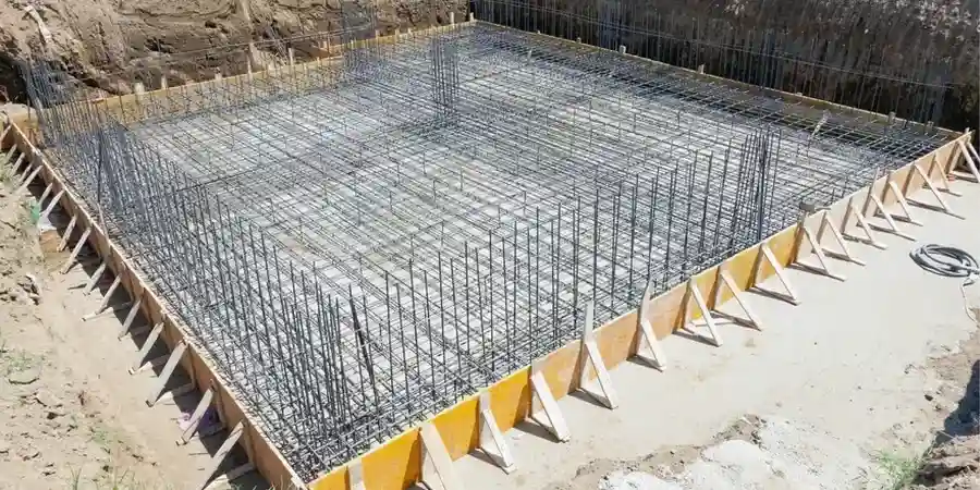
The most expensive mistake we see in Leon County is treating a mat foundation as a simple thickened slab and skipping the soil-structure interaction analysis. A contractor pours a uniform 18-inch mat with two layers of rebar, but no one has modeled how the variable subgrade modulus—stiff over limestone, soft over clay—bends the slab moments in ways the uniform design never anticipated. Within three years, the slab cracks at column lines where negative moment exceeds the section capacity, and the owner is chasing leaks through a foundation that cannot be retrofit economically. The second error is ignoring seasonal moisture fluctuation in the active zone: a mat placed on desiccated clay that later rehydrates can lift the entire structure if the dead load is insufficient to counteract swell pressures that exceed 5,000 psf. We require suction-controlled swell tests and a moisture-conditioning plan before the mud mat goes down, because Tallahassee’s shrink-swell potential is real and it does not self-correct.
Reference standards
ASCE 7-22 (Minimum Design Loads), IBC 2021 (Florida Building Code adopted edition), ACI 318-19 (Structural Concrete for Foundations), ASTM D2435 (Consolidation), D4546 (Swell), D2487 (Classification)
Additional services
Geotechnical Site Characterization
SPT borings, CPT soundings, and Shelby tube sampling to map the spatial variability of the Hawthorne Group clays and limestone across the building footprint.
Laboratory Testing Program
One-dimensional consolidation, swell, and triaxial CIU tests to determine stiffness, heave potential, and effective stress strength parameters for the design model.
Mat Foundation Analysis and Design
Finite element or Winkler-spring modeling to compute bending moments, shear forces, and contact pressures under dead, live, wind, and seismic load combinations per ASCE 7.
Construction Support and Subgrade Inspection
Proof-rolling observation, moisture conditioning verification, and reinforcement placement review prior to the mat pour.
Typical parameters
Questions and answers
When is a mat foundation necessary instead of spread footings in Tallahassee?
A mat becomes necessary when column loads are heavy and the bearing stratum is erratic—common in the Hawthorne Group where limestone pinnacles and soft clay pockets alternate over short distances. If more than 30% of the footing area would exceed the allowable bearing pressure or if total differential settlement is predicted above ¾ inch, a rigid mat is the standard solution. It also makes sense when the water table is high and individual footing excavations would require extensive dewatering.
How do karst conditions affect mat foundation design?
Karst introduces the risk of voids and pinnacles that create point-bearing conditions. A properly designed mat bridges these features by distributing column loads over a wide area, reducing the stress intensity on any single limestone high. We supplement the geotechnical investigation with resistivity profiling or seismic refraction to identify potential cavities before the mat is designed, because finding a void after the pour is a problem no amount of rebar solves.
What does a mat foundation design package cost for a commercial building?
For a typical commercial project in Tallahassee, the geotechnical investigation and mat foundation design package ranges from US$1,150 to US$4,630 depending on the building footprint, number of borings required, and complexity of the soil-structure interaction model. A single-story retail pad on uniform clay sits at the lower end; a multi-story structure on karst with variable subgrade requires a more detailed analysis and falls toward the upper range.
How do you verify the subgrade is ready before the mat is poured?
We require a proof-roll with a loaded dump truck or smooth-drum roller to identify soft spots, plus nuclear density testing to confirm compaction. Moisture content of the exposed clay must be within 2% of the optimum from the Proctor curve to minimize post-construction heave. Our engineer walks the excavation before the vapor barrier goes down—every time, no exceptions.