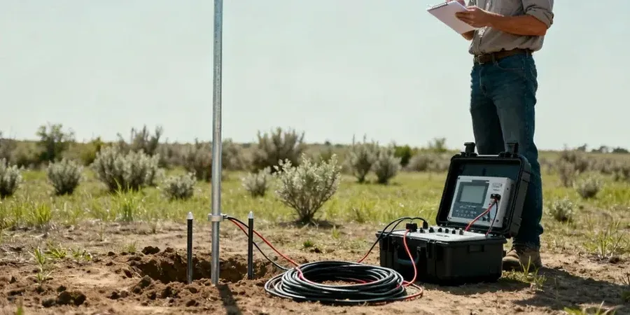
Tallahassee’s geology doesn’t read like the rest of Florida. The Red Hills region sits on ancient marine terraces capped with sands and clays that dissolve unevenly into the underlying Hawthorne Group, creating karst features and erratic water tables. When a project moves into the northeast quadrant near the Cody Scarp, the transition from well-drained uplands to wetter lowlands can shift subsurface resistivity profiles by an order of magnitude within a hundred feet. We run vertical electrical sounding lines using a 4-pin Wenner array to map those transitions before foundations go in. The data feeds directly into IBC Chapter 18 site classification and helps engineers decide whether a deeper MASW survey is needed to quantify shear-wave velocity across the same transect.
Electrical resistivity is the only non-invasive method that can trace a clay confining layer beneath dry sand without a single drill rig on site.
Our approach and scope
Local ground factors
The mistake we see too often is relying on a single boring to characterize a karst site in Leon County. When limestone pinnacles and clay-filled solution channels alternate across a footprint, one boring might hit solid rock while the next hits 12 feet of soft raveling clay. Electrical resistivity grids catch that lateral variability because the current path spreads across a volume, not a point. Skipping VES in these conditions leads to differential settlement surprises, overexcavation costs, or—worst case—a sinkhole repair bill that could have been avoided with a $700 geophysical survey. For bridge approaches over the Ochlockonee floodplain, we also flag low-resistivity zones that indicate organic silts prone to long-term consolidation.
Video overview
Reference standards
ASTM D6431 Standard Guide for Using the DC Resistivity Method, ASTM G57 Standard Test Method for Field Measurement of Soil Resistivity Using the Wenner Four-Electrode Method, IBC Chapter 18 Soils and Foundations, FDOT Specification 455 for geophysical site characterization, NIST IR 85-3273 resistivity reference data
Additional services
Single VES Sounding
One vertical electrical sounding point with Wenner array, ideal for determining depth to bedrock or water table at a single building location.
2D Resistivity Profile
Multiple electrodes along a survey line produce a continuous cross-section of subsurface resistivity for road alignments and utility corridors.
Soil Corrosivity Assessment
Resistivity measurements at pipe depth used to classify soil corrosivity per ASTM G57 for buried utilities and grounding system design.
Karst and Cavity Detection
Grid-based resistivity surveys designed to locate air-filled or clay-filled cavities in the Hawthorne limestone beneath proposed foundations.
Typical parameters
Questions and answers
How deep can VES investigate in the Tallahassee Red Hills clay?
It depends on the clay’s moisture content and the array layout. In the Red Hills, surface clays are often conductive, which limits current penetration. With a maximum Wenner spread of 250 feet, we typically reach 80 to 100 feet in dry sand over limestone, but only 50 to 70 feet when thick saturated clay sits near the surface. We adjust electrode spacing on-site after reviewing the first few readings.
What does a VES survey cost for a single-family lot in Tallahassee?
For a standard single-station VES on a residential lot in the Tallahassee area, the cost runs between US$680 and US$1,040 depending on access conditions, desired depth, and whether we include a soil corrosivity analysis. Larger 2D lines are priced by the linear foot after we see the site layout.
Can resistivity testing distinguish between air-filled and clay-filled cavities?
Yes, that’s one of the main reasons we use VES in Leon County’s karst terrain. Air-filled cavities show up as high-resistivity anomalies because air is an insulator. Clay-filled solution channels, on the other hand, appear as low-resistivity zones—often more conductive than the surrounding limestone. Combined with a boring log for calibration, the contrast is usually clear enough for engineering decisions.